Book Overview
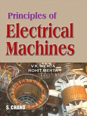
The Book Principles of Electrical Machines Book By VK Mehta and Rohit Mehta is an ideal text for students who look to gain a current and clear understanding of the subject as all theories and concepts are explained with lucidity and clarity. Succinctly divided in 14 chapters, the book delves into important concepts of the subject which include Armature Reaction and Commutation, Single-phase Motors, Three-phase Induction motors, Synchronous Motors, Transformers and Alternators with the help of numerous figures and supporting chapter-end questions for retention.
Book Name – Principles of Electrical Machines Book By VK Mehta and Rohit Mehta
Author – VK Mehta and Rohit Mehta
Publisher – S. Chand
Language – English
Paperback – 550 Pages
Key Features
- Conceptual understanding is given preference with theories being explained in clear and concise points.
- 1100+ figures and examples provide comprehensive support to all concepts explained.
- Close to 750 in-text tutorial problems, chapter-end short answer questions and MCQs provide apt practice to all concepts explained.
Book Contents
- Electromechanical Energy Conversion
- D.C. Generators
- Armature Reaction and Commutation
- D.C. Generator Characteristics
- D.C. Motors
- Speed Control of D.C. Motors
- Testing Of D.C. Machines
- Transformer
- Three-Phase Induction Motors
- Circle Diagrams
- Single-Phase Motors
- Alternators
- Synchronous Motors
- Special-Purpose Electric Machines
1. ELECTROMECHANICAL ENERGY CONVERSION
Electromechanical energy conversion – electromechanical energy conversion devices – features of electromechanical energy conversion – energy balance equation – energy in magnetic system – energy and coenergy – field energy and mechanical force – linear system – rotating electric machines – motors and generators – basic construction of electrical machines – commonly used electrical machines – multiply – excited magnetic system.
2. D.C GENERATORS
Generator principle – simple loop generator – action of commutator – construction of DC generators – general features of D.C armature windings – commutator pitch (yc)-pole –pitch – coil span or coil pitch (ys) – full – pitch coil – types of D.C armature windings – further armature winding terminology – generals rules for D.C armature windings – relations between pitches for simplex lap winding – simplex wave winding – multiplex windings – function of commutator and brushes – E.M.F equation of a D.C generators – armature resistance (Ra)- types of D.C generators – separately excited D.C generators- self-excited D.C generators – brush contact drop – electromechanical energy conversion in a generator – losses in a D.C.machine – constant and variable losses – power stage – condition for maximum efficiency . .
3. ARMATURE REACTION AND COMMUTATION
Armature reaction – geometrical and magnetic netural axes – explanation of armature reaction – demagnetizing and cross –turns per pole (ATd/pole)- cross magnetising ampere –turns per pole (ATc/pole) –compensating Windings- AT/pole for compensating windings – commutation – calculation of Reactance voltage – methods of improving commutation – Resistance commutation – E.M.F commutation – interpoles or compoles- Equalising connections – Important facts about D.C. Generators.
4. D.C.GENERATORS CHARACTERISTICS
D.C. Generator characteristics- open circuit characteristics of a D.C Generator – characteristics of a separately excited D.C. Generator- voltage build –up in a self –excited Generator –critical field Resistance for a shunt Generator –critical Resistance for a series Generator –characteristics of series Generator –characteristics of a shunt Generator –critical external Resistance for shunt Generator –How to draw O.C.C.at different speeds?-critical speed (Nc )- conditions for voltage build-up of a shunt Generator –compound Generator characteristics –voltage Regulation –need for parallel operation of D.C. Generator –conditions for parallel operation of shunt Generators –connecting shunt Generators in parallel –load sharing by shunt Generators in parallel –parallel operation of compound Generators –parallel operation of series Generators –D.C. Generators specifications –frame size versus speed of Electrical machines.
5. D.C MOTORS
D.C motor principle – working of D.C motor-back or counter E.M.F – significance of back E.M.F – voltage equation of D.C motor – power equation –condition for maximum power – types of D.C motors – armature torque of D.C motor shaft- torque (Tsh)-brake horsepower (b.h.p) – speed of a D.C motor – speed relation –speed regulation – torque and speed of a D.C motor-armature reaction in D.C motors –commutation in D.C motors –losses in a D.C motor –efficiency of a D.C motor –power stages –D.C motor characteristics – characteristics of shunt motors – characteristics of series motors –compound motors –comparison of three types of motors – applications of D.C motors – trouble in D.C motors
6. SPEED CONTROL OF D.C MOTORS
Speed control of D.C motors –speed control of D.C shunt motors –speed control of D.C series motors – series-parallel control –Electric braking –speed control of compound motors –necessity of D.C motors starter –Types of D.C motors starters –three-pointer starter –four –pointing starter –grading of starting Resistance –shunt motors –starter step calculation for D.C shunt motor.
7. TESTING OF D.C MACHINES
Efficiency of a D.C machine –Efficiency by Direct Loading –Swinburne’s Method for Determining Efficiency –Regenerative or Hopkinson’s Test –Retardation or Running Down Test –moment of inertia (/) of the Armature –Electric Loading in Retardation Test.
8. TARNSFORMER
Transformer –Theory of an ideal Transformer –E.M.F Equitation of a Transformer –voltage transformation Ratio (K) –practical Transformer –practical transformer on No Load –ideal transformer on load –practical transformer on load –impedance Ratio –shifting impedance –Exact Equivalent circuit of a loaded Transformer –simplified equivalent circuit of a loaded transformer –Approximate Equivalent circuit of loaded transformer –Approximate Voltage Drop in a transformer –voltage Regulation –Transformer Tests –open –circuit or No –load Test –short –circuit or impedance Test –advantages of Transformers Tests –separation of components of core Losses –why transformer rating in kVA ? –sumpner or back –to –back Test –Losses in a transformer –Efficiency of a transformer –Efficiency from transformer Tests –condition for maximum Efficiency-output kVA corresponding to maximum efficiency –all-day (or energy) efficiency –construction of a transformer –types of transformer-cooling of transformers –transformer rating –autotransformer –theory of autotransformer-saving of copper in Autotransformer – advantages and disadvantages of autotransformers –applications of autotransformer – conversion of two –winding transformer into autotransformer – parallel operation of single- phase transformers –single- phase equal voltage ratio transferors in parallel –single –phase unequal voltage ratio transformers in parallel – three –phase transformer –three-phase transformer connections – three –phase transformation with two single-phase transformers – open – delta or V-V connection –power factor transformers in V-V circuit –applications of open – delta or V-V connection –scott connection or T-T connection –three phase transformers connection and phase shift –parallel operation of 3-phase transformers –applications or transformers-instrument transformers –current transformers (C.T)-potential transformers (P.T)-advantage of instrument transformers.
9. THREE-PHASE INDUCTION MOTORS
Three-phase induction motor-construction –rotating magnetic field due to 3-phase current-alternate analysis for rotating magnetic field-principle of operation –slip-rotor current frequency-effect of slip on the rotor circuit –rotor current –rotor torque starting torque (Ts)-condition for maximum starting torque-effect of change of supply voltage –starting torque of three-phase induction motors –motor under load-torque under running condition-maximum torque under running conditions- torque-slip characteristics –full –load , starting and maximum torques – torque – speed curbe of 3 phase induction motor-characteristics of squirrel –cage motors –speed regulation of inductions motors –power factor of induction motor – measurement of slip-power stages in an induction motor – induction motor torque –rotor output- induction motor torque equation – performance curbs of squirrel – cage motor –plugging of an induction motor –braking induction motor with direct current – induction generator – applications of induction generators-complete torque / slip curbe of induction machine – induction motor and transformer compared equivalent circuit of 3- induction motor at slips –equivalent circuit of the rotor-transformer equivalent circuit of induction motor –power relations- approximate equivalent circuit of induction motor – starting of 3-phase induction motors –methods of starting 3-phase inductions motors-methods of starting squirrel –cage motors – starting of slip-ring motors –slip-ring motors versus squirrel cage motors –induction motor rating –abnormal operations of 3-phase inductions motors – double squirrel- cage motors –equivalents circuit of double squirrel – cage motor
10. CIRCLE DIAGRAMS
Circle diagram for R-L series circuit –importance of circle diagrams-circle diagram of 3- induction motor –data required for circle diagram – tests to obtain data for circle diagram – construction of circle diagram –complete circle diagram of induction motor –maximum quantities from circle diagram-speed control of induction motors-speed control by changing number of stator poles-speed control by changing line frequency-speed control by changing applied voltage-speed control by changing rotor circuit resistance-speed control b injection voltage in rotor circuit-speed control by cascade connection- rotor rheostat starter for slip-ring motors-classes of squirrel- cage induction motors- crawling of induction motors- cogging – linear induction motor (LIM)-properties of linear induction motor
11. SINGLE-PHASE MOTORS
Types of singe-phase motors – single-phase induction motors-double field revolving theory-making single – phase induction motor self-starting –rotating magnetic field form 2-phase supply- split-phase induction motor-capacitor-start motor –capacitor – start capacitor- run motor –shaded –pole motor –equivalent circuit of single –phase induction motor – A.C series motor of universal motor – single –phase repulsion motor –repulsion – start induction-run motor – repulsion-induction motor-single-phase synchronous motors- reluctance motor – hysteresis motor
12. ALTERNATORS
Alternator – construction of alternator – alternation operation –frequency – A.C armature windings – armature winding of alternator – winding factors – E.M.F equation of an alternator – armature reaction in alternator – alternator on load – synchronous reactance (xs)- phasor diagram of a loaded alternator – voltage regulation – determination of voltage regulation – synchronous impedance methods – ampere – turn method-procedure for AT method – zero power factor method of potier method – – procedure for potier method-power output in cylindrical rotor power/power angle characteristics – effect of salient poles – too reactance concept for salient –poles machines – power develop in silent – pole synchronous generator – V curves for alternator – parallel operation of alternators – advantages of parallel operation of alternators- condition for paralleling alternator with infinite busbars – methods of synchronisation – synchronising action – synchronising power- alternators connected infinite busbars-effect of load on synchronising power – sharing of load current by two alternators in parallel –alternators on infinite busbars – effect of change of excitation and mechanical input – hunting
13. SYNCHRONOUS MOTORS
Constriction – some facts about synchronous motor –operating principle –making synchronous motor self –starting –equivalent circuit –motor on load –pull –out torque –motor phasor diagram –effect of changing field excitation at Constance load –phasor diagrams with different excitation- v curves for synchronous motor –power relations –motor torque –mechanical power developed by motor –power factor of synchronous motors –synchronous condenser –stopping synchronous motors –applications of synchronous motors –comparison of synchronous and induction motors.
14. SPECIAL –PURPOSE ELECTRICAL MACHINES
Stepper motor- permanent –magnet (PM) stepper motor –variable –reluctance (VR) stepper motor –Hybrid stepper motor –servomechanism –A.C servomotors –A.C. servomotors switched reluctance motor (SRM) –permanent –magnet DC motor –brushless D.C. motors.


